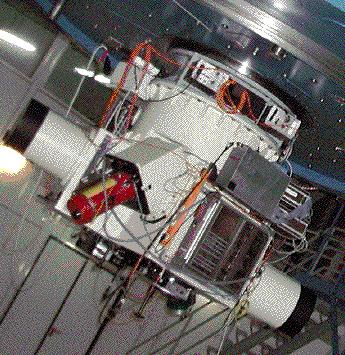

The Cassegrain Twin Spectrograph (TWIN) of the 3.5 m telescope has been designed for spectroscopic observations of point sources or extended objects at intermediate spectral resolution (typically 20 to 150 Ĺ/mm, 0.30 to 2.25 Ĺ/pix) in the wavelength range from 3200 to 11000 Ĺ. With an assumption of one pixel resolution (i.e. 15 micron) this leads to spectral resolutions in the range of R=3000 to R=14000. The TWIN includes two separate spectroscopic channels ("Blue" and "Red") behind the common entrance slit aperture. The light from the slit is divided into two beams by means of a dichroic mirror ( 4 beam dividers available with cross-over wavelengths near 4500, 5500, 6800, and 7500 Ĺ, respectively). Each channel consists of its own components including filter, shutter, collimator, grating, camera and detector. The optics of the "blue channel" and the "red channel" have been optimized for the regions from 3200 to 5500 Ĺ and from 5000 to 10000 Ĺ, respectively. The TWIN can be converted into a single-channel instrument by replacing the beam divider by a mirror acting as a "red beam selector".
Various reflectance gratings of 154 x 206 [mm] ruled area are available which can be used in either channel. The folded Schmidt-type cameras provide an external focal plane of 7 x 40 [mm] area, such that various CCD detectors can be easily attached to the TWIN. An eight-position aperture wheel in the focal plane of the telescope allows selection of various predefined slit widths. In each case the slit length is 240 arc sec. The aperture wheel is replaceable. Various spectral lamps and a continuum light source have been built-in (matching the exit pupil of the telescope) which can be selected for wavelength calibration or "flat fielding".
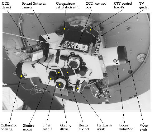
The electronics of the TWIN and of the two CCD detectors are controlled by a workstation via an EPICS data base system. The TWIN and the CCD cameras are operated by a graphical user interface.
The TV guiding and acquisition system of the 3.5m telescope will be used for viewing or guiding the object on the reflecting slit mask or for offset guiding. The autoguider can be used either on the slit view, acquisition field or the offset field.
The whole instrument (including the TV guider) can be rotated
on the Cassegrain instrument flange in order to select the
position angle of the entrance slit.
Rotation is performed normally using the command CASFL at the tecs35
console.
The PA of the the slit is PA(Slit) = PA (Cass) + 90.
The optical diagram is presented in Fig. 1-2:. The f/10 beam from the 3.5 m telescope enters the TWIN at its entrance slit aperture. A total of 8 different slit apertures, mounted on a replaceable aperture wheel, can be selected. The maximum length of the entrance slit is 210" (unvignetted) or 240" (vignetted up to 30% on one side).
The light reflected by the aluminized aperture mask (slit) is fed into the TV guiding and acquisition system of the telescope. A retractable mirror can be brought in front of the slit, in order to feed the light from the comparison/calibration unit onto the slit. In that case, all light from the telescope will be blocked from entering the spectrograph. The light beam from the comparison/calibration sources matches the f/10 beam from the telescope (same position of exit pupil). Each of the comparison/calibration light sources is selected by a rotatable diagonal mirror within the comparison/calibration unit.
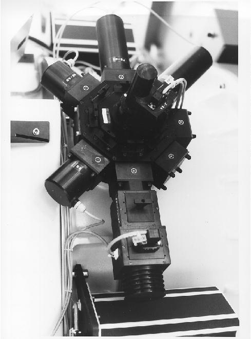
The light entering the TWIN through the slit is divided into two beams by means of a dichroic mirror, tilted 18 degrees. The cross-over regions for the 4 available beam dividers are near 4500, 5500, 6800, and 7500 Ĺ , respectively. The beam divider unit contains additional flat mirrors in order to bring each beam into its particular spectrograph channel. The light path and the optical components of either the "blue channel" or the "red channel" are nearly identical and will be described below. The beam divider unit can be removed from the TWIN and replaced by a "red beam selector" containing a single mirror. In that case all the light is fed into the red channel. Each spectrograph channel includes a filter carrier (for blocking unwanted spectral orders of the grating) and a shutter in the light path between the beam divider and the collimator. Each collimator is an off-axis parabolic mirror of 185 mm diameter and 1460 mm focal length. The collimator mirror can be moved (manually) in the direction of its axis in order to make focus corrections in the exit plane of the cameras of the TWIN.
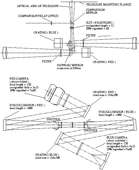
The collimated light is refracted towards the spectrograph
camera by (interchangeable) reflectance gratings of 154x206 mm2
ruled area. The angle between the incident and (central)
diffracted light beam is 37 degree. The diffraction angle of the grating
can be set with an accuracy of 3.6" (about 0.25 Ĺ at 36 Ĺ per mm).
Each camera is of the "folded Schmidt-type" consisting of a
corrector plate of 210 mm diameter, a spherical mirror of
210 mm diameter and 230 mm focal length, and a large diagonal
flat mirror between corrector and spherical mirror. The diagonal
mirror has a central hole, permitting the convergent beam
from the spherical mirror to reach the external focus (about
15 mm behind the exit flange of the camera housing). The curved
field of the camera is made flat by means of an aspheric field
flattener lens. (For the currently used CCD-detectors, i.e. SITe, 2000 x 800
pixel a 15 micron, these lenses are specifically designed serving as
windows of the CCD-dewars). The useful size of the camera field is
7mm x 40 mm.
| Scale at entrance slit | 1" = 170 µ |
| Length of entrance slit | 240" |
| Focal ratio of collimators | f/10 |
| Focal length of collimators | 1460 mm |
| Ruled area of gratings | 154 x 206 mm |
| Focal length of cameras | 230 mm |
| Maximum field of cameras | 7 x 40 mm |
| Scale at camera exit (slit direction) | 1" = 26.8 µ 1 pix = 0.56" |
| Slit apertures | Width ["] 0.9, 1.2, 1.5, 1.8, 2.1, 2.4, 3.6, 10.0 Length 240" |
| Position angle | Adjustable by rotating the spectrograph at the cassegrain flange |
| Order sorting | By beam splitter and/or colour filters |
| Beam splitters | Available at 450, 550, 680, and 750 nm |
| Filters for order separation | WG295, WG360, OG515, RG610, BG39, Calflex X1 |
| Detectors | SITe-CCD's with 2000 x 800 Pixel 15 µ (CCD) |
| Comparison lamps | ThAr, HeAr, FeNe, Ne |
| Flat fields | Quartz-halogen bulbs (+ various filters) (built-in). Dome light and screen |
| Grating list |
To start an usual observing run follow the next steps:
Press any button in the GUI to get a description of its function
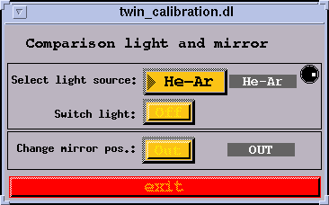
The comparison/calibration unit provides for 5 different light sources, to be selected by a rotatable diagonal mirror within that unit. The presently available sources are:
| Position | Light source |
| 1 | He-Ar glow lamp |
| 2 | Fe-Ne hollow cathod |
| 3 | Th-Ar hollow cathod |
| 4 | not used |
| 5 | not used |
| 6 | Incandescent lamp (for flat field) |
| 7 | Ne glow lamp |
Note: Individual light sources can be modified by color or neutral density filters to be inserted in front of the sources within the comparison/ calibration light unit (operation restricted to staff members).
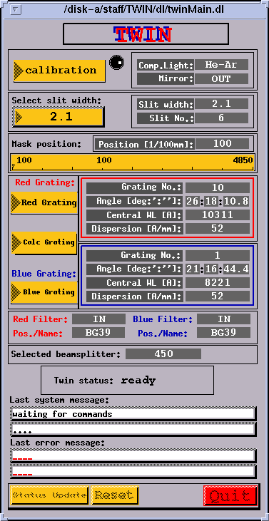
To manage this unit, click on TWIN-GUI "calibration" button and the next small GUI will appear:
| Position | Slit aperture | |
| mm | arc secs | |
| 1 | 1.00 x 40 | 5.9 x 240 |
| 2 | 0.15 x 40 | 0.9 x 240 |
| 3 | 0.20 x 40 | 1.2 x 240 |
| 4 | 0.25 x 40 | 1.5 x 240 |
| 5 | 0.30 x 40 | 1.8 x 240 |
| 6 | 0.35 x 40 | 2.1 x 240 |
| 7 | 0.40 x 40 | 2.4 x 240 |
| 8 | 0.60 x 40 | 3.5 x 240 |
The relation between the Grating angle THETA [degree] and the wavelength at the center of the spectrum WL [Ĺ] is given roughly by
where "m" denotes the spectral order and "a" the number of grooves
per mm of the grating.
The grating angle can be changed clicking on the "Red-Grating" or the "Blue-Grating" button and entering the new angle values in the small GUI that it is shown.
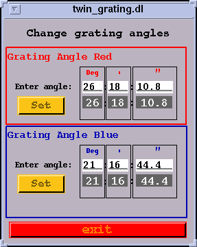
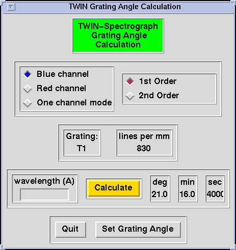
Anyway, it is easier and recommended to use the "Calc Grating" button. This way, after choosing the channel and order in the new GUI, just enter the central wavelength click on "Calculate" and "Set Grating Angle", and the grating will be accurately positioned.
Although most of the light of unwanted spectral orders it is blocked
by the dichroics, the transmission (or reflection) of these it is not
a 100% for the complete wavelength range. For this reason, in some
configurations, order separation filters are needed.
Filters can be inserted into the light beam of either channel using the filter
carriers of the TWIN. A carrier can take only one filter. The filter carriers
are operated manually using the handles at the bottom plate of the TWIN
Installing filters into the filter carriers is a delicate operation restricted to the authorized personnel.
Available filters for order separation: WG 295, WG 360, OG 515, RG 610, BG 39, Calflex X1.
At the TWIN-GUI can be read which filters are installed in both arms, and if these are in or out of the light beam
Actually four beam dividers are available for separation at 4500, 5500, 6800
and 7500 Ĺ.
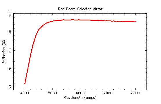
As can be seen in next graphics, the red part of the light beam it is not
100% transmitted. For this reason, and for some configurations (grating,
central wavelength, etc ...) some undesired reflections can appear.
The effect it is avoided when using the red beam selector mirror.
At the TWIN-GUI it is shown which one it is installed.
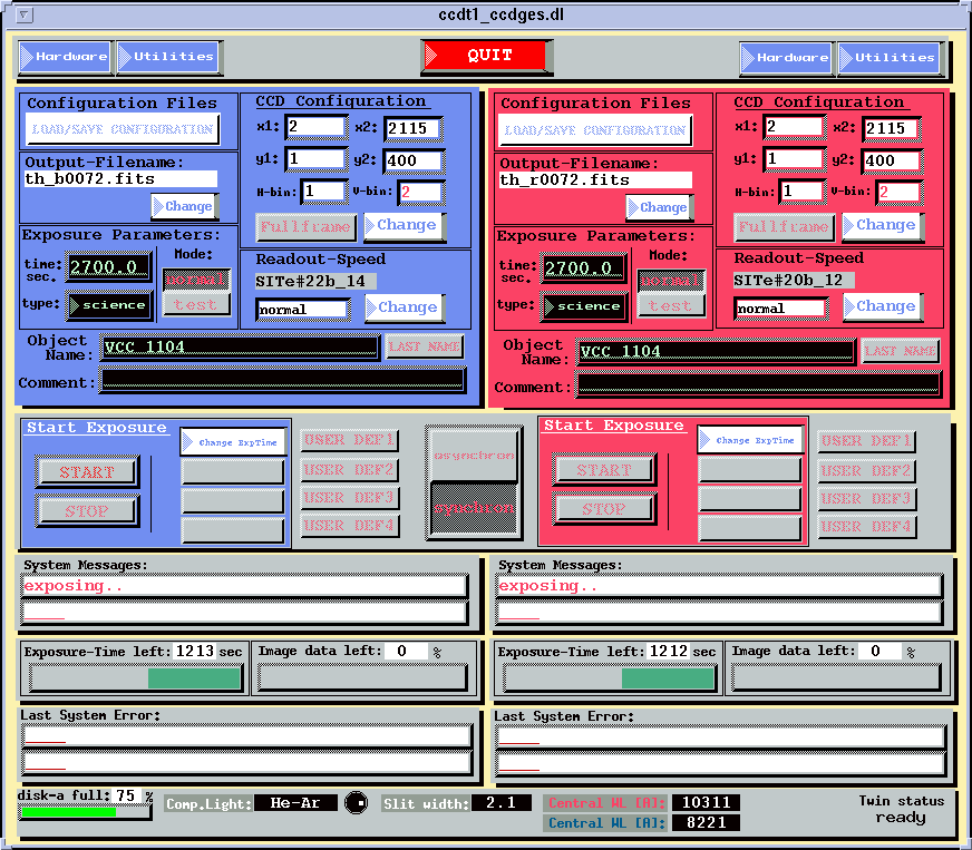
With this GUI we manage the two CCD-Cameras of TWIN spectrograph. Buttons and fields on the left part (blue background) are referred to the blue-arm camera and the ones on the right side (red background) to the red-arm camera. Description of any button or field can be get it clicking on it and some common characteristics are listed here:
 Choosing one of the entries will open the following popup-Windows:
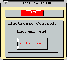
If you get many error-messages like "no serial connection" or
"timeout in select" or if you only get noise instead of an CCD-Image,
push this button and wait until you get the message in the System Messages
lines "Press start for a new exposure". Attention! The following 3 images
after the reset may have a slightly higher noise level!
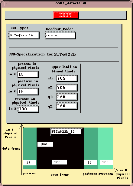
... with some detector information like chiptype, overscan, prescan and
postscan and upper limits for x and y.
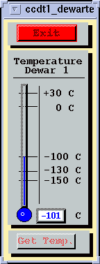
... with the actual Dewar Temperature. Pushing the button "Get Temp."
will update the information if possible.
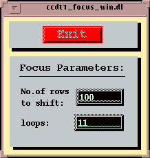
... with two entry fields: Number of rows to shift during a focus exposure
and the number of focus-loops.
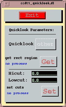
... with the toggle-button to switch between saoimage/saotng or another
quicklook-system like midas. If you push the button, the image will be
automatically loaded into saoimage or saotng if one of these programs is open.
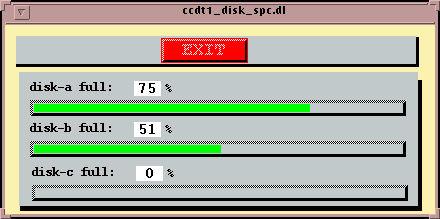
...will show the status of disks.
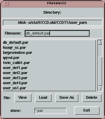
Here, you can load a saved parameter-file by double-click or
click & Load, save the actual parameters in a parameter-file
(give a Filename and press SaveAs), view the entries of a
parameter-file or delete a file.
Special: the 4 files user_def1-4.par are related with the 4 buttons
"USER DEF1-4" in the Main-Window. This means, if you save a configuration in
one of these files, you can load them by pressing the related button.
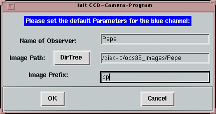
The text-field shows the last Image-Filename (except this is the first
exposure or something's gone wrong and the Filename has already been updated).
It will be checked and updated when starting an exposure. You can change the
prefix, image-path and observer-name in the window that will pop up after
pushing the "Change"-button.
Enter the desired exposure time into the entry-field "time". Accuracy
is up to 0.1sec. 0 sec is allowed.
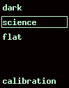
Choose (by pressing the right mouse button) the desired exposure-type. The
type is also saved as Fits-Keyword
A dark exposure means, the shutter is kept closed during the whole
exposure-time
A science exposure means, the shutter is open for the desired exposure time.
A flat exposure is the same as a science exposure, only the keyword in the
Fits-header will be different.
A calibration exposure is similar to flat o science exposure, but ensure that the
calibration lamp will switch on and mirror in when the exposure start (if it is not
done in advance).
The toggle-button "Mode" switches the Image-Filename between
test0001.fits and the specified Image Filename. The file test0001.fits
will always be overwritten and not incremented.
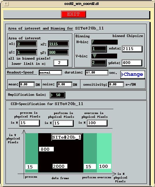
The text-fields show the actual area of interest (in x1/y1 x2/y2) plus the
binning information (H-bin means horizontal binning, V-bin vertical binning
factor).
The push-button "Full Frame" will set the the coordinates of the area
of interest to a full frame image at the selected binning.
If you want to change the x/y-parameters or the binning, push the button
"Change".
In the following popup-window you see the text-entry fields for the area of interest
and the binning. x1-y1 is the lower left corner and the lower limit for x is 2.
The fields for readout-speed, duration, mean, noise, sensitivity and gain
are not yet implemented.
The lower part of the configuration window shows some detector information like
chiptype, overscan, prescan and postscan in physical pixels (15 µ).
Actually only one readout speed it is available, labeled "normal". It takes
aprox. 55 secs. to read the full unbinned chip.
Enter into this text-entry field the Object Name of your observation. If
exposure mode "normal" is selected then any object name is required.
For "test" mode this field can be left blank.
The text-entry line for comments is saved twice as Fits-Keyword in the header
of the image file, one at the beginning of the exposure and the other at the
end. This means, you can enter comments about clouds, seeing, etc ... during
a longtime exposure.
When clicking on this button an exposure is started with the actual parameters.
Obtaining all the telescope and instrument information, as well as reserving
disk space for the image-file, it is done before the real exposure start and
takes only 2 or 3 seconds.
During exposures, the remaining exposure time is displayed as a green bar-graph
below the System Messages. If the remaining exposure time is greater than 3sec,
you can stop the exposure by pressing the STOP button.
Clicking on Change ExpTime a new window appears where the exposure time
can be changed.
With resume, you re-open the shutter (not during dark-exposures of
course) and continue with the exposure.
The dark-time in the FITS-Header will differ from the exposure-time.
With read out, you terminate the exposure and start immediately the
readout process. The exposure-time in the FITS-Header will be the actual
elapsed time with shutter open.
With abort, you dismiss the exposure completely.
When the asynchron button is pressed up, you can manage the blue and red CCDs
cameras in a completely independ way.
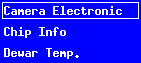
Camera Electronic
Chip Info
Dewar Temp.
Utilities
 Choosing one of the entries will open the following popup-Windows:
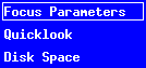
Focus Parameters
Quicklook
Disk-Space
LOAD/SAVE CONFIGURATION
Change Output Filename
Exposure parameters
CCDs Configuration
Readout Speed
Object Name
This entry is deleted every time after an exposure. You can get the last name
back by pushing the button LAST NAME. The object name is saved as
Fits-Keyword in the header of the image file.
Comment
Start Exposure
This will close the shutter and activate the 4 buttons on the right:
Change ExpTime, Resume, Readout and Abort .
Synchron Mode
Working in synchron mode anything you type or select in the input-fields
(black background) of one camera will be writted in both. And more important,
when clicking on a START button the exposure will start in both cameras.
Attention !! synchron mode is not recommended for short exposures (few seconds)
because some times the shutter doesn't work properly.
Santos Pedraz Marcos
Last modified: Mon Jun 18 02:30:45 GMT 2001