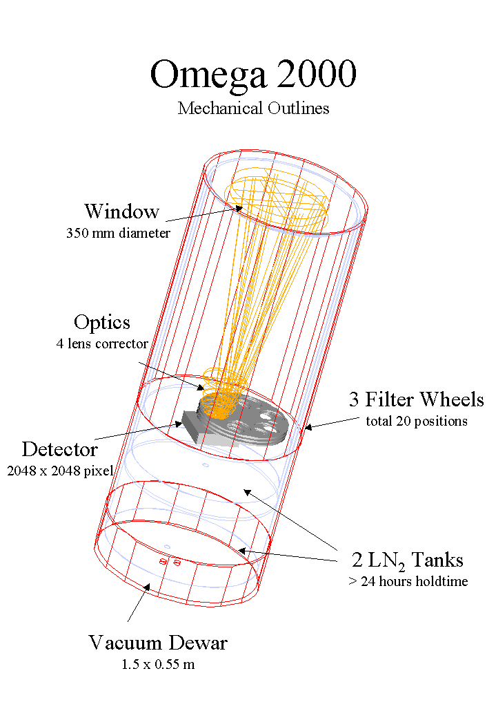
For some years, Calar Alto has played a leading role in near infrared astronomy, first with the MAGIC cameras (1993) and more recently with the Omega Prime (1996) and Omega Cass (1997) instruments. Omega Prime, at the prime focus of the 3.5m telescope, is the workhorse of wide field infrared surveys at Calar Alto, with a field of view of 6.8' (at 0.4"/pix). Omega Cass, at the Cassegrain focus of the same telescope, has three different cameras offering three different pixel scales of 0.1, 0.2 and 0.3"/pix. This instrument offers grism spectroscopic modes in addition to direct imaging, and sees a lot of use in conjuction with the ALFA adaptive optics module.
A major factor driving the design of infrared instruments is the detectors. At the time that they were built, Omega Cass and Omega Prime used the largest near infrared detectors then available, namely the 1024*1024 HgCdTe (Mercury-Cadmium-Tellurium) HAWAII-1 arrays made by the Rockwell Science Center in California. Now, Rockwell is in the process of producing the first science-grade HAWAII-2 arrays, with 2048*2048 pixels. These will be very similar to the HAWAII-1 arrays, apart from having slightly smaller pixels (18.0 rather than 18.5 micron) and more readout channels to permit faster readout. They have a high quantum efficiency between 0.8 and 2.58 microns (see Fig 2 below).
To keep Calar Alto at the forefront of infrared astronomy, the MPIA has decided to develop a new near infrared camera based on these arrays. A contract was signed with Rockwell in May 1999 in which we will receive a science-grade HAWAII-2 array in summer 2001. The decision was made to build a wide field imaging instrument with the largest field of view possible. Whilst other instrument capabilities, such as multi-object spectroscopy over a wide field of view, would also be desirable from a scientific point of view, these would significantly add to the cost and timescale of the project, as well as compromising the imaging mode to some degree.
Given the emphasis on achieving a wide field of view, it was decided to place it at the prime, rather than the Cassegrain, focus of the 3.5m telescope. This enables excellent image quality to be obtained over the whole field (see figures 3-6 below). The pixel scale is 0.45"/pix, a compromise between maximising the field of view and not seriously undersampling the PSF in good seeing conditions. This corresponds to a field of view of 15.4' (236 sq arcminutes), over five times that of Omega Prime. The design is similar to that of Omega Prime, in particular in that in order to achieve excellent optical quality over the large field of view, the instrument has no pupil reimaging optics and no cold Lyot stop. This means a potentially lower sensitivity in the thermal infrared (i.e. longer than about 2 microns, in the K bands). However, we have investigated a number of baffling schemes which should reduce the amount of warm background (from the floor and dome) seen by the detector. Initial estimates suggest that the sensitivity will be at least as good as Omega Prime, if not slightly better.
Omega 2000 will replace Omega Prime as the wide field near infrared survey instrument at Calar Alto. Spectroscopy and high spatial resolution imaging will continue to be offered by Omega Cass and ALFA. In parallel, a greatly increased capability for doing deep, wide field optical surveys will be provided by LAICA described in a separate article in this newsletter.
First light with Omega 2000 is expected towards the end of summer 2001, with the instrument open to the community from the first semester in 2002. Table 2 shows how Omega 2000 compares with other existing and upcoming near infrared facilities.
A very important decision which still needs to be made is the exact choice of filters for the camera. Infrared instruments have to be kept cold to reduce the thermal background, and this means that all of the filters must be mounted inside the cold cryostat. Frequently heating and cooling the cryostat degrades the detector, and the plan at Calar Alto is to temperature cycle the cryostat no more than once per observing semester. This means that all filters must be permanently mounted inside the cryostat. Furthermore, the filters we require are relatively large, and will have to be custom made, meaning that they will both be expensive and take many months to make. If you have an interest in specific filters, in particular narrow band filters, please get in touch with me soon to communicate your wishes. There is only space for 16 filters, so you should not automatically assume that your particular filter will be available. For the broad band filters we are considering following the 2MASS filter specifications (J,H and Ks), given that this survey will be the largest NIR all sky survey for many years to come. Additionally a Z filter similar to the z' filter plus CCD response of the Sloan Digital Sky Survey will be used to extend the broad band coverage of the instrument into the blue (see this paper for specification of the SDSS filters) . A "standard" full K filter will also be provided, but no other filters are yet definitely planned. In summary, you can only be certain that Z, J, H, Ks and K filters will be available, so now is the time for your requests!
More details on the design of Omega 2000 can be found in a recent paper. The Omega 2000 project web page will contain more details as the project progresses. And, of course, feel free to contact me directly (calj@mpia-hd.mpg.de).
|

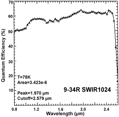
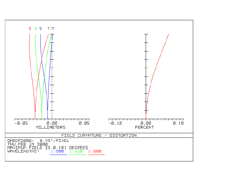
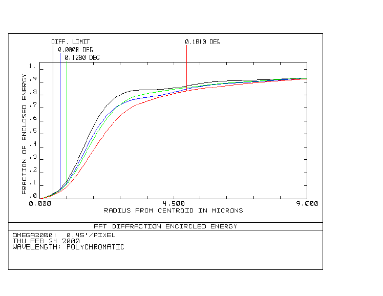 Fig 4: J-band encircled energy
This shows the radial
distribution of the energy in the image of a point source on the
detector. The blue, green and red lines are for positions at the
centre, edge and corner of the detector. The black line is the
diffraction limit. Note that the detector pixels are 18 micron
square. Thus over 90% of the energy for an ideal point source is
contained within a single pixel (0.45"). Of course, seeing will
degrade this.
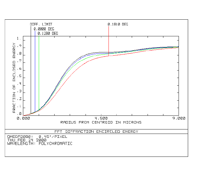 Fig 5: H-band encircled energy
See caption to Fig 4 for more details
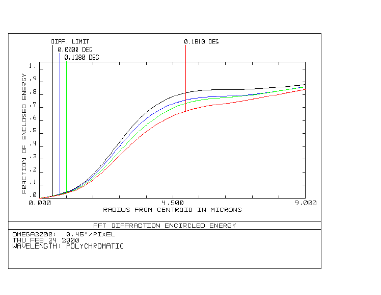 Fig 6: K-band encircled energy
See caption to Fig 4 for more details