Contents
- Preface
- General Information
- Operation of individual components of the TWIN
- Operation of TWIN and CCD cameras
-
Appendix
Preface
This user's guide is intended to serve as a reference document for users of the 3.5 m Cassegrain Twin Spectrograph (TWIN) in connection with a CCD detector system.A description of the CCD-dectors in use can be found in the CCD detector overview .
List of Figures
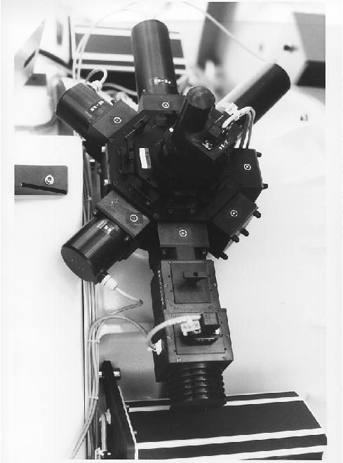
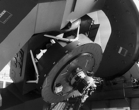
- Fig. 2-1: The Cassegrain Twin Spectrograph with CCD detectors on the 3.5 m telescope.
- Fig. 2-2: Graphical User Interface for TWIN and CCD control ( Under construction !)
- Fig. 2-3: Optical layout of the TWIN
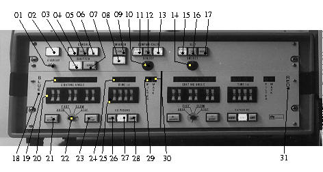
- Fig. 3-1: Electronic control boxes on the TWIN housing
- Fig. 3-2: Comparison/Calibration light source unit
List of Tables
- Table 2-1: Basic instrument parameters of the TWIN
- Table 3-1: Comparison/Calibration light sources
- Table 3-2: Slit apertures
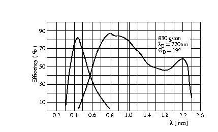
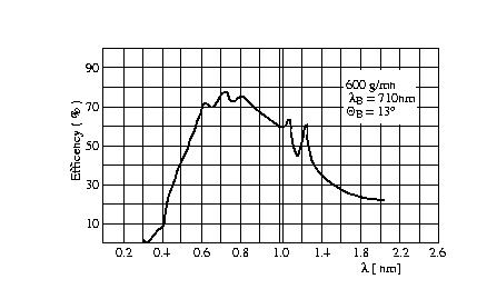
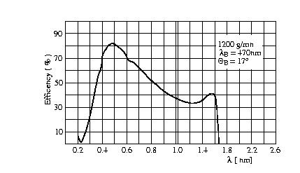
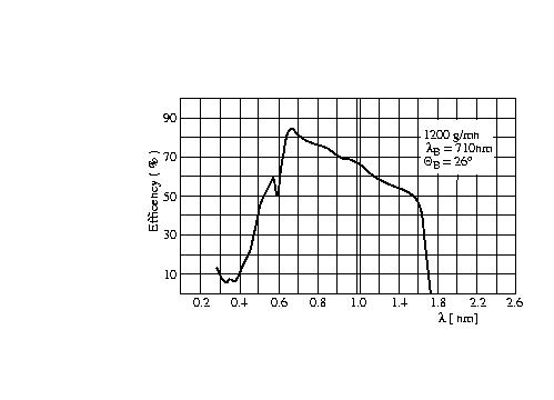
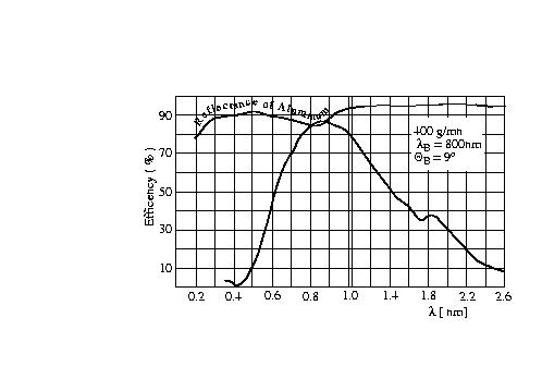
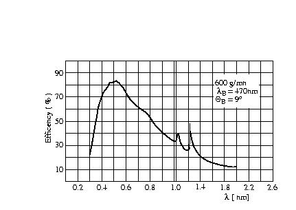
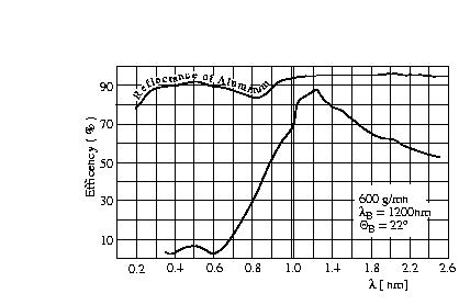
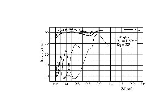
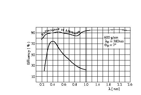
- Table 3-3: List of gratings
- Table 3-4: Grating angles as function of wavelength for various gratings
General Information
Basic Configuration of the TWIN
The Cassegrain Twin Spectrograph (TWIN) of the 3.5 m telescope ( Fig. 2-1:) has been designed for spectroscopic observations of point sources or extended objects at intermediate spectral resolution (typically 20 to 150 Ĺ per mm) in the wavelength range from 3200 to 11000 Ĺ. With an assumption of one pixel resolution (i.e. 15 micron) this leads to spectral resolutions in the range of R=3000 to R=14000. The TWIN includes two separate spectroscopic channels ("Blue" and "Red") behind the common entrance slit aperture. The light from the slit is divided into two beams by means of a dichroic mirror ( 4 beam dividers available with cross-over wavelengths near 4500, 5500, 6800, and 7500 Ĺ, respectively). Each channel consists of its own components including filter, shutter, collimator, grating, camera and detector. The optics of the "blue channel" and the "red channel" have been optimized for the regions from 3200 to 5500 Ĺ and from 5000 to 10000 Ĺ, respectively. The TWIN can be converted into a single-channel instrument by replacing the beam divider by a mirror acting as a "red beam selector".
Various reflectance gratings of 154 x 206 [mm] ruled area are available which can be used in either channel. The folded Schmidt-type cameras provide an external focal plane of 7 x 40 [mm] area, such that various CCD detectors can be easily attached to the TWIN. An eight-position aperture wheel in the focal plane of the telescope allows selection of various predefined slit widths. In each case the slit length is 240 arc sec. The aperture wheel is replaceable. Various spectral lamps and a continuum light source have been built-in (matching the exit pupil of the telescope) which can be selected for wavelength calibration or "flat fielding".
The electronics of the TWIN and of the two CCD detectors
are controlled by a workstation via an EPICS data base system.
The TWIN and the CCD cameras are operated by a graphical user
interface.
The TV guiding and acquisition system of the 3.5 m telescope
will be used for viewing or guiding the object on the reflecting
slit mask or for offset guiding. The autoguider can be
used either on the slit field or the offset field.
The whole instrument (including the TV guider) can be rotated
on the Cassegrain instrument flange in order to select the
position angle of the entrance slit.
The optical diagramm is presented in
Fig. 2-3:.
The f/10 beam
from the 3.5 m telescope enters the TWIN at its entrance slit
aperture. A total of 8 different slit apertures, mounted on a
replaceable aperture wheel, can be selected. The maximum length
of the entrance slit is 210" (unvignetted) or 240" (vignetted
up to 30% on one side). The light reflected by the aluminized
aperture mask is fed into the TV guiding and acquisition system
of the telescope. A retractable mirror can be brought in front
of the slit in order to feed the light from the comparison/
calibration unit onto the slit. In that case, all light from
the telescope will be blocked from entering the spectrograph.
The light beam from the comparison/calibration sources matches
the f/10 beam from the telescope (same position of exit pupil).
Each of the comparison/calibration light sources is selected by
a rotatable diagonal mirror within the comparison/calibration
unit.
The light entering the TWIN through the slit is divided into two
beams by means of a dichroic mirror, at an incidence angle of
18 degree. The cross-over regions for the 4 available beam dividers
are near 4500, 5500, 6800, and 7500 Ĺ , respectively.
The beam divider unit contains additional flat mirrors in order
to bring each beam into its particular spectrograph channel.
The light path and the optical components of either the "blue
channel" or the "red channel" are nearly identical and will be
described below. The beam divider unit can be removed from the
TWIN and replaced by a "red beam selector" containing a single
mirror. In that case all the light is fed into the red channel.
Each spectrograph channel includes a filter carrier (for
blocking unwanted spectral orders of the grating) and a shutter
in the light path between the beam divider and the collimator.
Each collimator is an off-axis parabolic mirror of 185 mm
diameter and 1460 mm focal length. The collimator mirror can be
moved (manually) in the direction of its axis in order to make
focus corrections in the exit plane of the cameras of the TWIN.
The collimated light is refracted towards the spectrograph
camera by (interchangeable) reflectance gratings of 154x206 mm2
ruled area. The angle between the incident and (central)
diffracted light beam is 37 degree. The diffraction angle of the grating
can be set with an accuracy of 3.6" (about 0.25 Ĺ at 36 Ĺ per mm).
Each camera is of the "folded Schmidt-type" consisting of a
corrector plate of 210 mm diameter, a spherical mirror of
210 mm diameter and 230 mm focal length, and a large diagonal
flat mirror between corrector and spherical mirror. The diagonal
mirror has a central hole, permitting the convergent beam
from the spherical mirror to reach the external focus (about
15 mm behind the exit flange of the camera housing). The curved
field of the camera is made flat by means of an aspheric field
flattener lens. (For the currently used CCD-detectors, i.e. SITe, 2000 x 800
pixel a 15 micron, these lenses are specifically designed serving as
windows of the CCD-dewars). The useful size of the camera field is
7mm x 40 mm.
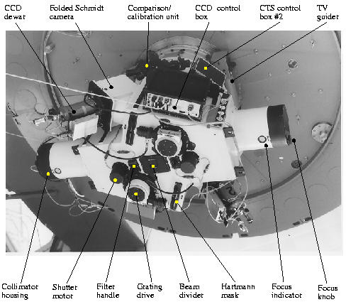
FIG 2-1: The TWIN Spectrograph with CCD-detectors on the 3.5m
telescope.
Graphical User Interface for TWIN and CCD control
( Under construction !)
Optical Diagram
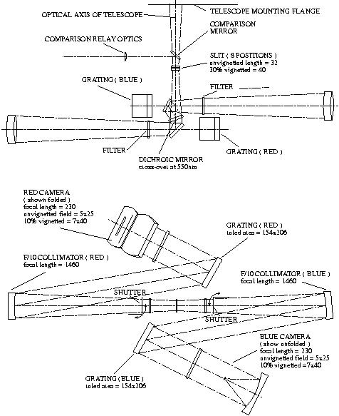
FIG 2-3: Optical diagram of the TWIN. Indicated dimensions
are quoted in mm.
Summary of basic instrument parameters
Table 2-1:
Basic instrument parameters of the TWIN: